A Bend Test may be carried out on a tensile testing machine with the help of certain attachments as described later in this section. A bend test is an easy and inexpensive test to apply. The method is fast and shows most weld faults quite accurately.
Bend tests may be used to find a number of weld properties such as:
- Ductility of the welded zone
- Weld penetration
- Fusion
- Crystalline structure (of the fractured surface)
- Strength.
The bend test assists in determining the soundness of the weld metal, the weld junction and the heat affected zone. The test shows the quality of the welded joint. Any cracking of the metal will indicate false fusion or defective penetration.
The stretching of the metal determines to some extent its ductility. Fractured surface shows the crystalline structure. Large crystals usually indicate wrong welding procedure or poor heat treatment after welding. A good weld has small crystals.
To conclude, the bend test is an easy and useful method of comparing one welded joint with another of the same type and of revealing abnormalities and defects at or near the surface in tension.
Types of Bend Tests
Bend tests may be categorized as:
- Free Bend Test
- Guided Bend Test
- Transverse bend test (Root bend test and Face bend test)
- Longitudinal bend test
- Side bend test.
Free Bend Test
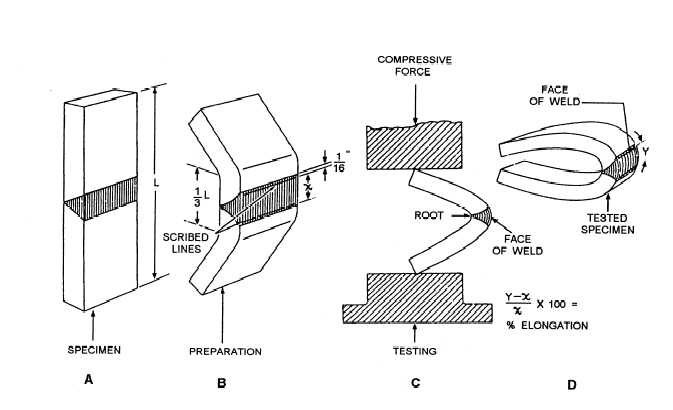
Free bend test determines the ductility of weld metal. Free bend test may be conducted on a tensile testing machine or a vise capable of exerting a sufficiently large compressive force. For bend test, the test pieces are cut from the plate so as to include the weld.
The specimen (after the gauge length has been scribed on the face of the weld) may be bent initially by using a hammer. This is known as the initial bend.
After giving an initial bend on to the specimen, it is placed in another fixture. The bending is continued until a crack or open defect exceeding 1.5 mm in any direction appears on the convex surface of the specimen. If no crack appears, the specimen shall be bent double
Guided Bend Test
A guided bend test shows surface imperfections near and in the weld bead. A guided bend test is performed on the specially designed jig. The specimen to be tested is first ground smooth so that all weld reinforcement is removed. The specimen is then placed across the die supports and bent by depressing the plunger until it forms the shape of a U.
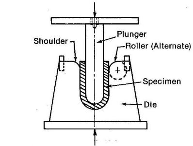
In a Guided Root Bend test, the specimen is placed in the jig with the root on the reverse of the metal not coming into direct contact with the plunger.
In a Guided Face Bend test, the specimen is placed in the jig with the face on the reverse of the metal not coming into direct contact with the plunger.
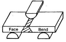
Transverse Bend Test
A transverse bend test is useful in qualifying welders because it quite often reveals the presence of defects that are not detected in tension test.
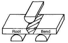
The specimen is bent by the movement of a plunger or former. Suitable gauge marks if scribed at the outside surface of the specimen help estimating % elongation. In a Face bend test the specimen is placed with its face down . The former is depressed until the piece becomes D shaped in the die (a guided bend test). If upon examination, cracks greater than 3 mm appear in any direction, the weld is considered to have failed.
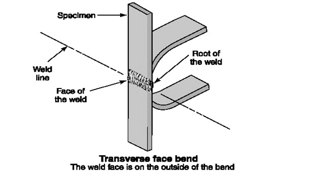
In a Transverse Face Bend test, the specimen is placed in the jig with the face on the outside of the bend. Face bend tests are used to inspect the degree of fusion, the absence or presence of inclusions and the weld porosity, if any.
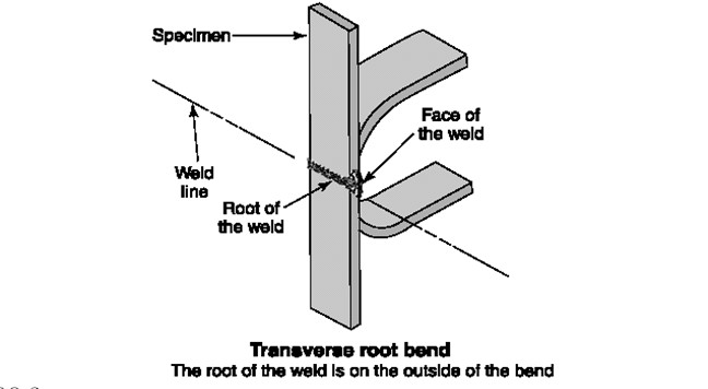
In a Transverse Root Bend test, the specimen is placed in the jig with the root on the outside of the bend or in just the reverse position of the face bend test. The results must show no cracks to be acceptable. Root bend tests are used primarily to determine the degree of weld penetration.
Non-uniform properties along the length of the specimen can cause non-uniform bending. An over matching weld metal strength may prevent the weld zone from conforming exactly to the bend die radius and may force the deformation out into the base metal, causing less than the desired elongation of the weld. With under matching weld strength, the specimen may tend to kink in the weld and there occurs more severe elongation in the weld. The specimen for transverse bend test is of the full thickness of the material at the welded joint and the upper and lower surfaces of the weld are dressed flush with the base metal surface.
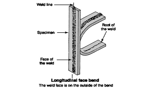
Longitudinal Bend Test
The problems of weld mismatch (as described in transverse bend test) can be avoided by using longitudinal bend specimens in which the weld runs the full length of the bend specimen; the bend axis being perpendicular to the weld axis.
In longitudinal bend test, all zones of the welded joint (i.e., weld, heat affected zone and the base metal) are strained equally and simultaneously. This test is generally used for evaluations of joints in dissimilar metals. Specimens for longitudinal bend test are prepared in the same manner as for transverse bend tests.
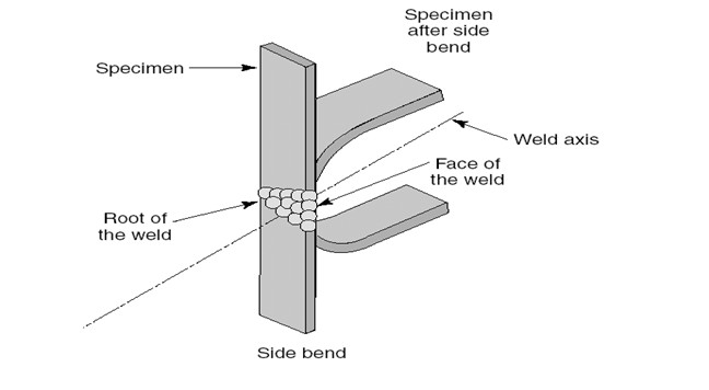
Side Bend Test
Side bend specimens strain the entire weld cross section and are thus especially useful for exposing defects near mid thickness that might not contribute to failure in face or root bend tests. A side bend test determines the soundness of the welded joint in cross section. This test is used for relatively thick sections (over 19 mm), since in this test the entire weld thickness may be included in the test.
The width of the test specimen shall be the full thickness of the material at the welded joint and the upper and lower surfaces of the weld shall normally be dressed flush with the surface of the base metal. The specimen is placed over the supports and it is bent by the downward movement of the former. The specimen is examined after the test and type and location of flaws, present, if any, are noted.